

Reverse Engineering.
At Laser Scanning, we provide more than just a scanning solution. We specialise in reverse engineering physical products and turning them into highly accurate CAD models for various applications. Typically the main principle of reverse engineering is to understand how a product works. This information can then be used to recreate the product like for like or improve it with added features and functionality. More often than not, the main goal of reverse engineering is to either re-create a product because it is no longer available or create a similar product in a more cost-effective manner.
-

Reference Model
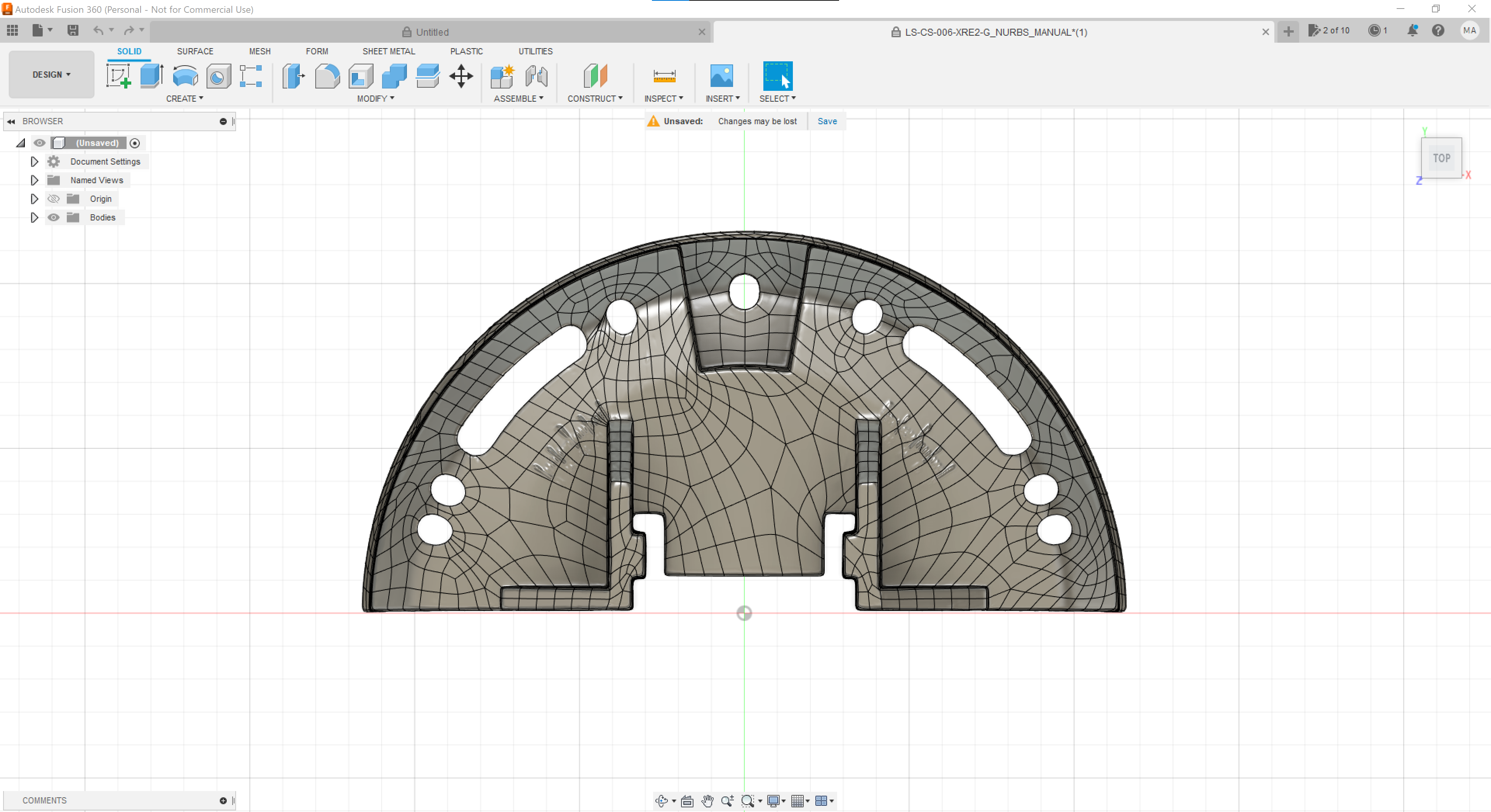
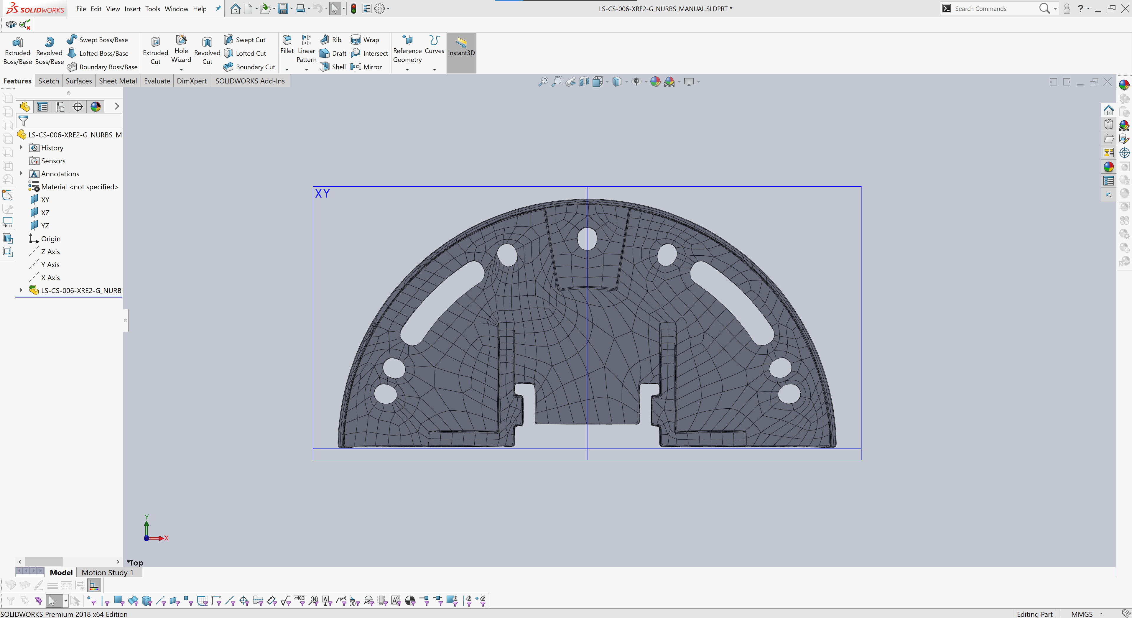
A reference model often referred to as a NURBS (Non-uniform rational basis spline) model is one of the lowest levels of reverse engineering we can offer. As the name suggests, this level of processing directly references the scan data by automatically creating a patchwork surface model. However, be aware that because this model directly references the original scan data, it will carry through any defects or wear on the part into the final model. One of the main benefits of a reference model is that it can easily be imported into your existing CAD package, such as Solidworks, Fusion, Catia etc. We find our customers opt for the reference model option if they have an in-house Design Engineer with reverse engineering experience. They can sit this model in the background of their existing CAD package and parametrically recreate it themselves.
A reference model may also be a good option if no feature alterations are required, for example, when developing blister packaging for parts. It is also an effective inspection and comparison tool and is often used in part analysis and mould-flow simulation.
-
Parametric CAD
Parametric CAD modelling is the gold standard for creating complex parts and assemblies, used in daily production by thousands of companies throughout the UK. You may be familiar with parametric modelling if you have experience with CAD packages such as Solidworks, Fusion 360, Inventor and many more. The principles of parametric modelling allow you to create a 3D CAD model in which you capture design intent using features and constraints.
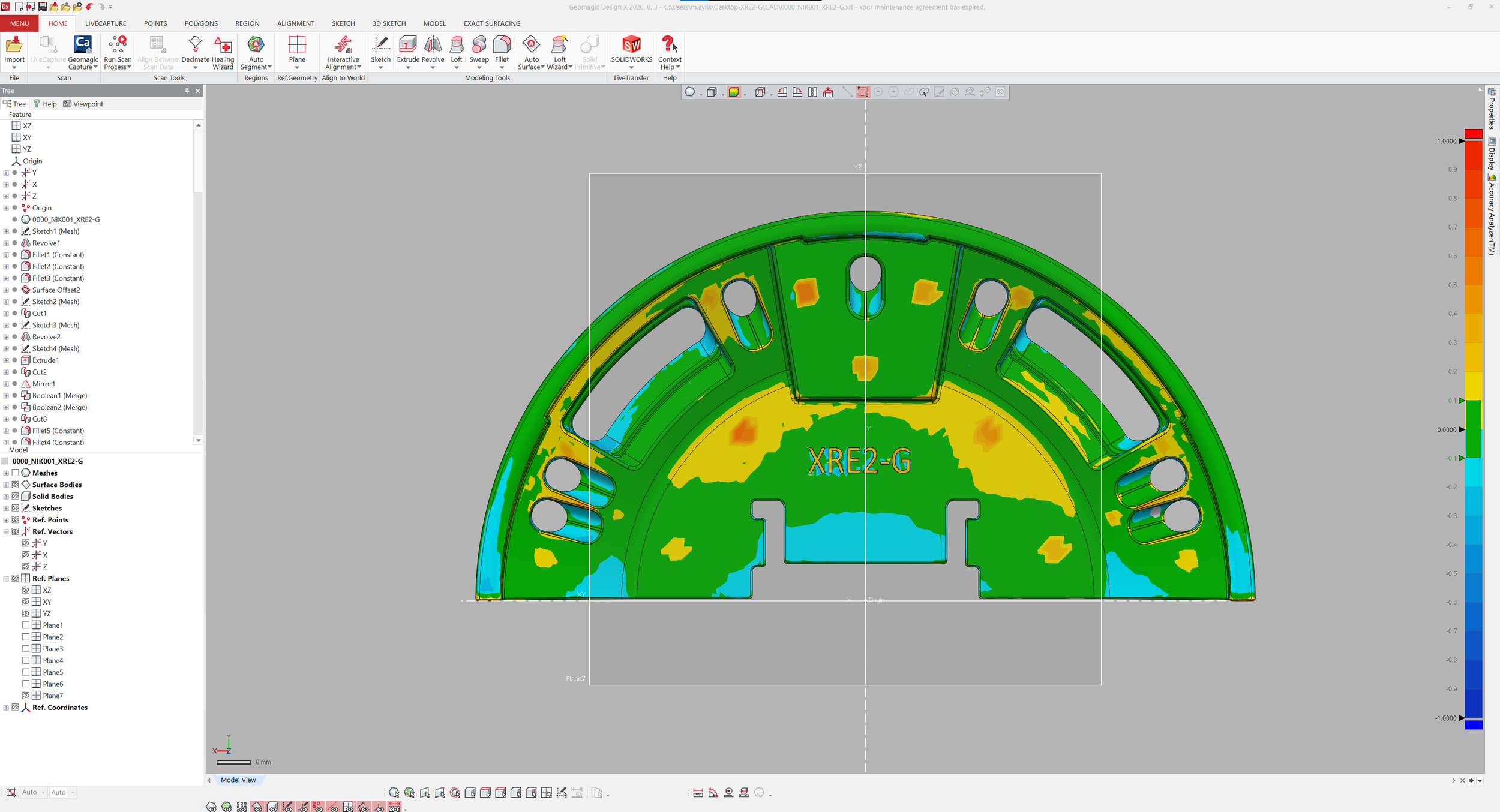
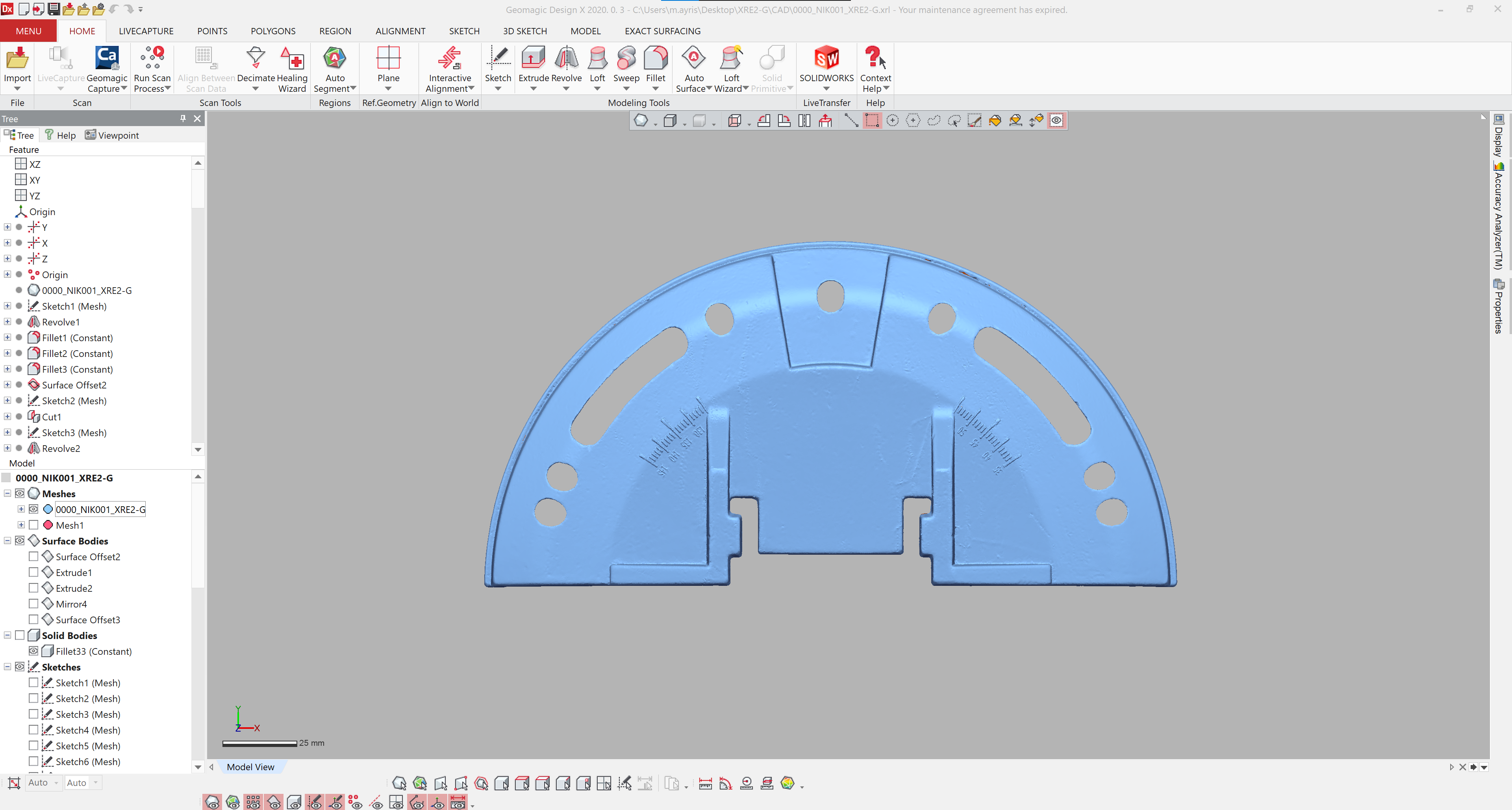
When we parametrically reverse engineer your parts, we use a specialised CAD package called Geomagic Design X. This CAD software lets us directly reference our highly accurate scan data to ensure a precise CAD model. Throughout the reverse engineering process, we constantly inspect the deviation level between scan and CAD with a visual +- heat map.
If you are looking to remanufacture your part(s), we strongly advise parametric modelling over reference modelling, as this gives us complete control over design for manufacturing principles. We work with a wide range of manufacturing partners, so we can take your part from laser scanning to mass production or anywhere in between.
Parametric modelling also allows us to return the part to its original design intent and remove any defects or wear. We also can make any required modifications or provide various design iterations.
Reference Model.
A reference model often referred to as a NURBS (Non-uniform rational basis spline) model is one of the lowest levels of reverse engineering we can offer. As the name suggests, this level of processing directly references the scan data by automatically creating a patchwork surface model.
Reference Model.
You may consider a reference model if you are looking to accurately reference a part - for example, when developing blister packaging or an over mould. It can also be used as an effective inspection and comparison tool and is often used in part analysis or mould-flow simulation.
If you are looking to remanufacture a part, it is important to consider how the part may have originally been created. If this is a machined or injection moulded part, parametric modelling will more than likely be a better option. However, if the part is a handmade, freeform or organic part reference modelling may be more applicable.
We also find some customers take advantage of our reference models if they have an in-house Design Engineer or Design team as the reference model can be used to parametrically reverse engineer in their existing CAD package.
Download our reference model sample pack below, but please be aware reference files have a much larger file size than parametric.
Scan to Reference Data.
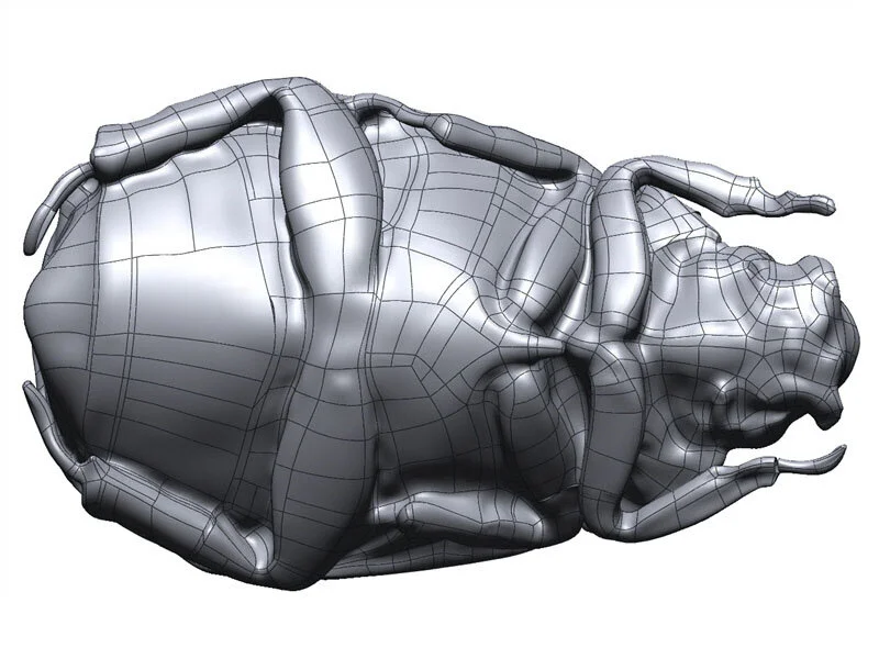
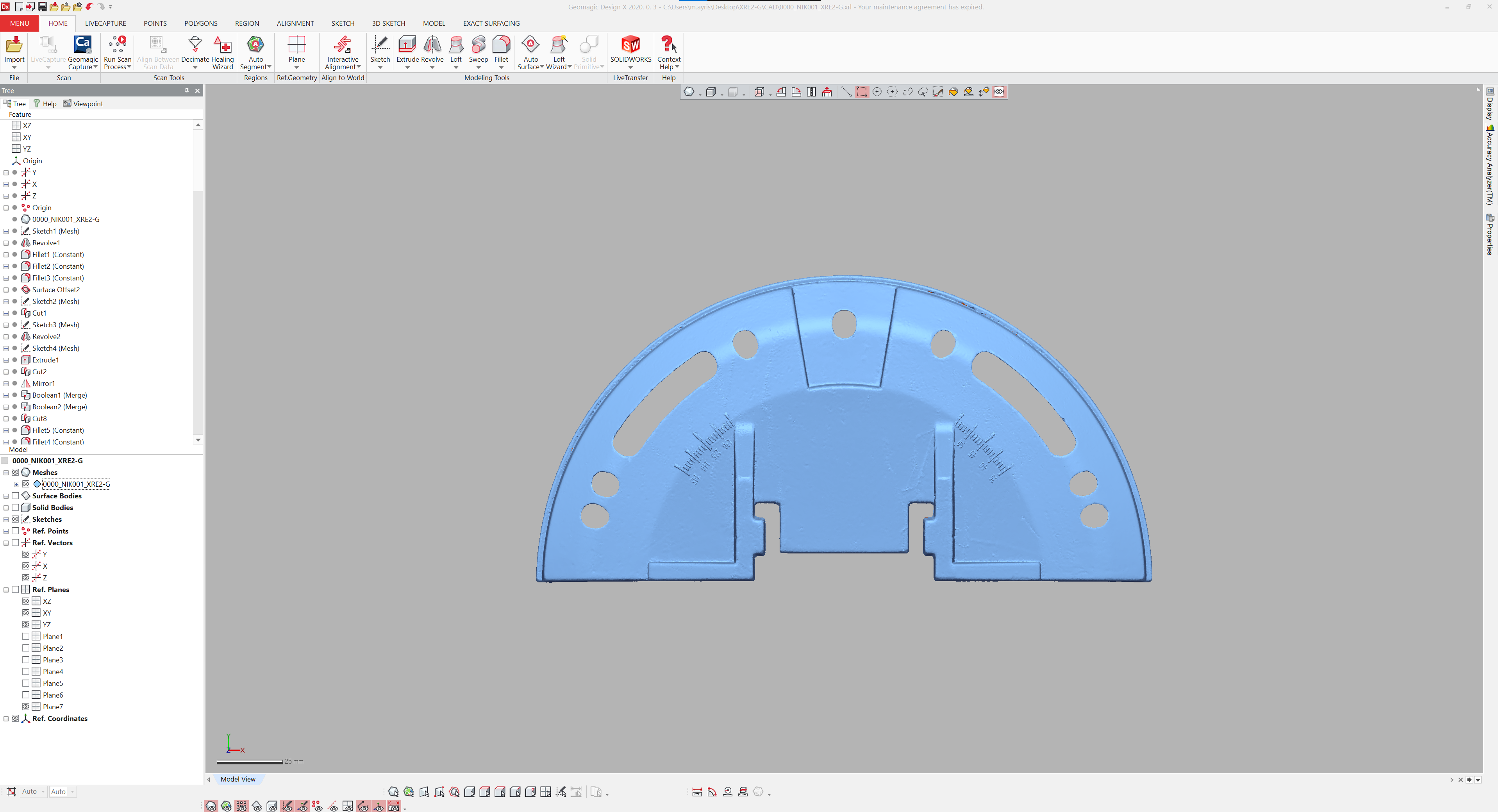
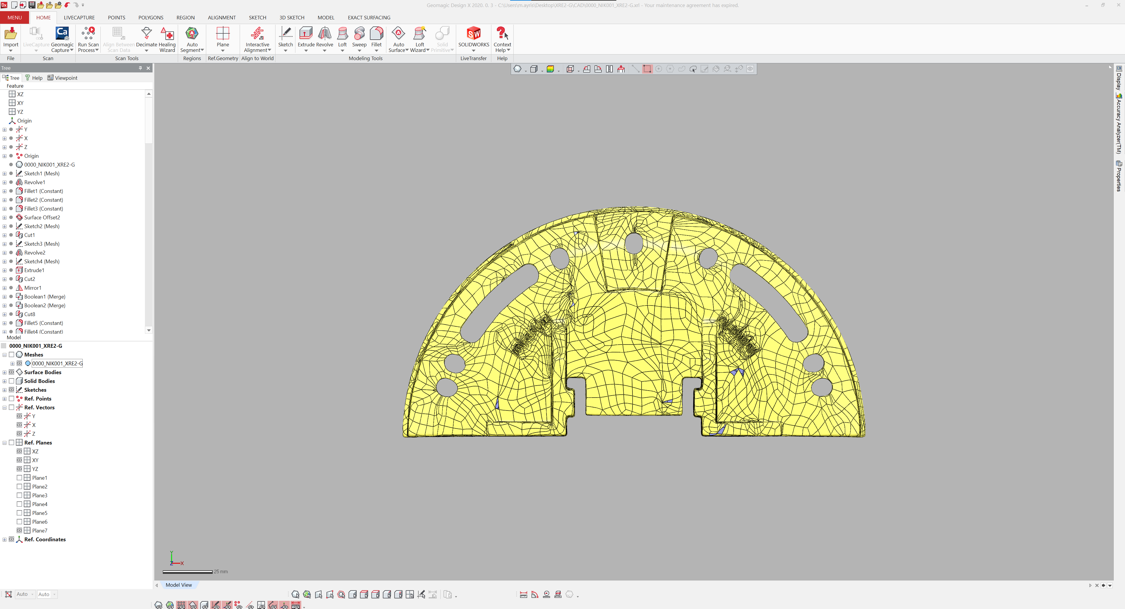
We use a CAD package called Geomagic Wrap to convert your highly accurate scan data (blue) into a patchwork surface model (yellow). Geomagic Wrap allows us to control various parameters to ensure your final CAD model is accurate but also a manageable file size.
File Import.
Reference data can be supplied in almost any required CAD format. However, we typically supply in .stp, .iges & .xt allowing you to import into most any existing CAD package.
Parametric CAD.

Parametric CAD.
Parametric CAD modelling has many benefits over reference models. The main benefits are:
Optimised 3D model.
Remove any manufacturing defects.
Remove any wear.
Parts original design intent.
Much smaller file size.
Easily modify the part.
CAD format export (.stp, .iges, .xt).
Native file formats - Solidworks (if required).
Manufacture drawings (if required).
Scan to Parametic CAD.
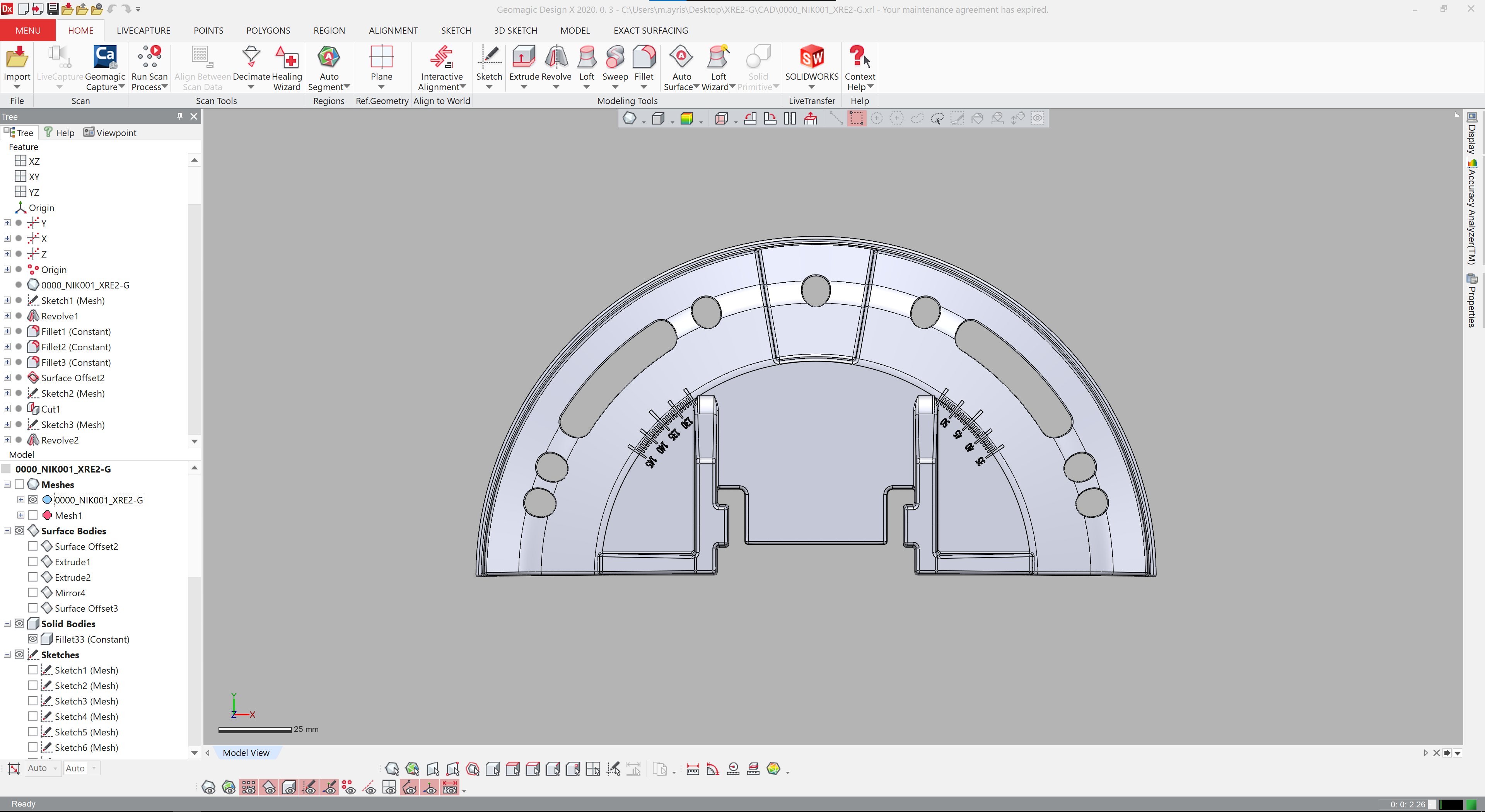
We use a CAD package called Geomagic Design X to reference your highly accurate scan data (blue) and reproduce your CAD model using typically parametric CAD techniques such as sketches, extrudes, loft etc. You can see how much cleaner the parametric CAD model is (grey) when compared to the reference model example above.
Why Choose Parametric?
Typically, we find that 9/10 of our customers require a parametric model as it has many more capabilities than a reference model. If you are looking to remanufacture an existing part, you will need a parametric model, as this model will have been optimised for design for manufacture. We will bring the part back to its original design intent by removing any defects or wear and giving the part rounded constrained dimension.
CAM (Computer Aided Manufacturing) software can also reference parametric models' features, such as fillets, extrudes, etc., making manufacturing quicker and much more cost-effective.
Parametric models also a considerable small file size than reference models.